Version 3.0 Development
- vac023

- Oct 20, 2019
- 3 min read
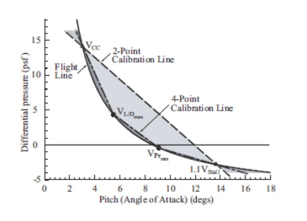
Our initial work was software based—just tap into the Dynon AOA signal and find the 60% lift point. That turned out to be more complicated than first blush. The first hurdle was accurately processing the serial output from the EFIS and the second the nature of the Dynon AOA calibration. The good news is that the 60% rule turned out to be proportional…Assuming the calibration captured L/Dmax (not all do), finding 60% of whatever % maximum lift was detected at stall worked well. While the Dynon system provides excellent stall warning when properly calibrated, the Dynon logic is challenged to accurately map the parabolic flight line when AOA is plotted against differential pressure. This shortcoming is what lead us to press ahead with the 2nd Generation design. The engineering has been happening fast, and we are on the third iteration (Version 3.0) of the Gen 2 system. Our very first box (Version 1.0) is connected to an Alpha Systems probe and mounted on the inspection plate in my RV-4 where it serves as an independent, calibrated test reference. We built five Version 2.0 systems, one of which is the primary AOA computer in my airplane. My airplane also retains the original Dynon system and can accommodate a calibrated test boom as well. In full-up test configuration, it’s got five independent AOA systems on-board. Getting all of that data recorded simultaneously at high baud rates has been quite a challenge and required a few months of work, but we are there now. We can record all of the data with accurate GPS time stamps for later analysis.

The primary difference between Version 2.0 and Version 3.0 is the addition of a serial interface, and optimization of board design to reduce component footprint and optimize circuit design. Version 3.0 retains the three pressure sensors of Version 2.0 (two differential sensors and one reference sensor). Unfortunately, current FAA guidance precludes plumbing the static sensor into the aircraft system in certified airplanes; so one of the objectives of beta test will be to determine the efficacy (or necessity, depending on the type of probe fitted) of this sensor. Initial testing will simply leave the port open to the cockpit static environment in which it is installed (think “alternate static source”). In experimental airplanes, plumbing into the primary static system isn’t an issue, and may be the best way to derive accurate AOA across the entire aircraft flight line for certain sensor configurations. Our initial findings are that the Alpha Systems type probe (adjustable 45 degree "wedge") will work fine with just the differential pressure sensors; but a Dynon type probe works better when the differential pressure is normalized against dynamic pressure, which uses the signal from the third (static) sensor.
We need to revise the resource sections of the website to include the new Version 3.0 information; and we still haven’t completed our migration to a consolidated Fly ONSPEED GitHub address—no excuse. Our current efforts have used our limited time for aircraft modification, flight test; and now, low-rate initial production of 25 units and harnesses for beta test. Yours truly will plug away at the website as time allows, and the smart, engineering types will get our software consolidated. Our initial flight test has shown that we’ve got the physics right; so it will be interesting to see what happens as we get systems into the field—especially in a flight training environment.
Although our ultimate objective is to automate calibration, my next blog will explain the "hard tune" physics-based calibration we are currently using to map the aircraft flight line and the flight test techniques required.


Comments